
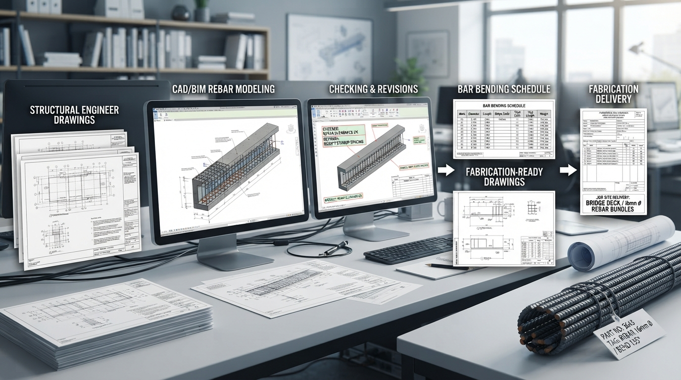
Rebar Detailing Process: From Structural Drawings to Fabrication (Step by Step)
Ever wonder how a 400-page set of a structural engineer’s drawings becomes a bundle of bent rebar that fits perfectly on site? That’s the rebar detailing process and it has zero room for error. A single misplaced #8 bar can stall a pour and cost thousands. Here’s the short answer: the rebar detailing process is the step-by-step translation of structural design drawings into fabrication-ready rebar shop drawings and bar bending schedules (BBS). It starts with a thorough review of the engineer’s structural drawings, moves into 3D modeling and connection detailing, gets checked against ACI standards, and ends with shop drawings delivered to the fabricator with revision management running the whole way through.
Below, I’ll walk you through each stage of the rebar detailing process the way our detailing team actually runs it on real U.S. commercial projects including the common rejection causes we see from DOTs and design engineers, and the software that makes it all work.
What Does the Rebar Detailing Process Actually Cover?
The rebar detailing process sits between structural design and field construction. The design engineer sizes the members and specifies bar sizes, spacing, and development lengths. The detailer turns that intent into buildable instructions: exact bar shapes, cut lengths, lap splice locations, hook dimensions, and placement geometry for every element, footings, columns, beams, slabs, walls, stairs, and retaining structures.
In practice, a complete rebar detailing covers:
- Reading and interpreting the structural drawing set (plans, sections, schedules, and general notes)
- Modeling the reinforcement in 3D, member by member
- Resolving congested areas and detailing all connections
- Producing bar bending schedules with quantities per mark
- Generating shop drawings for fabrication and placing drawings for the field
- Coordinating revisions through RFIs, addenda, and bulletins
Every stage feeds the next. Miss something in Stage 1, and you’ll pay for it in Stage 6.
Who Is Responsible for Rebar Detailing?
The rebar detailing workflow involves several parties, but each has a distinct responsibility:
- Structural Engineer: Designs the structural reinforcement and specifies bar sizes, spacing, development lengths, laps, and other design requirements.
- Rebar Detailer: Interprets the engineer’s design intent and converts it into constructible rebar shop drawings, placing drawings, and bar bending schedules (BBS). The detailer does not redesign the structure.
- Fabricator: Uses the approved shop drawings and BBS to cut, bend, tag, and bundle reinforcement bars according to the specified dimensions and bar marks.
- Field Crew: Uses the placing drawings and bar tags to position and install the reinforcement correctly before concrete placement.
- RFIs and Coordination: When drawings contain conflicts, missing information, or conditions that cannot be detailed as shown, the detailer raises an RFI to obtain clarification from the engineer before proceeding.
Understanding these responsibilities is important because design drawings and rebar shop drawings serve different purposes. The engineer establishes the structural design; the detailer translates that design into fabrication and installation-ready documentation.
The 7 Stage Rebar Detailing Process: A Step-by-Step Walkthrough
Stage 1: Review and Interpret the Structural Drawings
Before any modeling starts, the detailer performs a full document review: architectural backgrounds, structural plans, sections, elevations, foundation details, column schedules, beam schedules, and the general structural notes. On a typical mid-rise, that’s 150+ sheets. The goal of this step in the rebar detailing process isn’t just reading. It’s catching conflicts early. Common findings at this stage:
- Bar sizes or spacing that physically don’t fit within member depths
- Missing development lengths where beams frame into columns
- Inconsistent footing elevations between the civil and structural sets
- Open items the engineer needs to clarify (these become RFIs)
A disciplined review at the start of the rebar detailing process prevents most downstream rework. It’s the cheapest insurance in the entire workflow. Detailers log every discrepancy before modeling.
Stage 2: Build the 3D Reinforcement Model
Next in the rebar detailing process, the detailer builds the reinforcement model using dedicated detailing software. Tekla Structures is widely used for rebar modeling, while SDS/2, AutoCAD-based tools, and Revit are also common on U.S. projects. Bars are modeled at true 1:1 scale to accurately represent their geometry, placement, and relationships with surrounding structural elements.

The 3D model captures key reinforcement information, including:
- Bar marks, sizes, and grades: Reinforcing steel is detailed according to the bar sizes, grades, and material specifications required by the project documents.
- Bar geometry: Straight bars, standard hooks, stirrups, ties, and special bends.
- Concrete cover: Required cover based on exposure and structural conditions.
- Lap splice lengths: Required splice lengths based on bar size, grade, concrete strength, and applicable design requirements.
This coordinated model becomes the foundation for producing rebar shop drawings, placing drawings, and the bar bending schedule (BBS).
Stage 3: Detail the Connections and Congested Zones
Connections are where the rebar detailing process earns its keep and where shop drawings services most often get rejected. Beam-column joints, moment frame connections, corbels, embeds, and shear walls demand bar-by-bar resolution. The detailer checks that every bar fits alongside its neighbors with adequate clearance for concrete placement and vibration.
For precast connections and specialty embeds, this stage often loops back to the engineer with RFIs. Good detailers resolve congestion in the model before issuing drawings that fabricators appreciate.
Stage 4: Generate the Bar Bending Schedule (BBS)
With the model complete, the next step in the rebar detailing process is to generate the bar bending schedule (BBS), the fabricator’s cutting and bending list. Each bar mark receives a dedicated line item containing the information needed for accurate fabrication. CRSI’s Manual of Standard Practice, 31 Edition provides industry guidance on reinforcing-steel detailing, fabrication, and placing.
| Field | What It Tells the Fabricator |
| Bar mark | Unique identification, such as 4B12 |
| Size & grade | Bar size and steel grade, such as #4, #5, #6, or Grade 60 |
| Shape code | Standard shape designation |
| Dimensions | A, B, C, and other required leg dimensions |
| Cut length | Total length required before bending |
| Quantity | Number of identical bars required |
| Weight | Total weight of bars for that mark |
The BBS drives material ordering, cutting, and fabrication planning. An accurate bar bending schedule reduces material waste, improves cutting efficiency, and helps prevent costly emergency reorders during construction.
Stage 5: Quality Check and QA Review
No rebar detailing workflow is complete without a formal QA review. Reinforcement detailing and presentation should also follow the applicable project requirements and industry guidance, including guidance from the American Concrete Institute (ACI).
Before the drawings are issued, the checker reviews the reinforcement model and documentation to identify geometry, coordination, and fabrication issues. The checker verifies:
- Hook and bend dimensions are correctly detailed
- Lap splice and development length requirements are properly incorporated
- Bar marks, tags, and callouts are consistent between the drawings and BBS
- Dimensions reference clear work points that the field crew can measure from
- Reinforcement fits within the specified concrete cover and available member dimensions
- All RFI responses, addenda, and approved revisions are incorporated
A two-pass review, geometry first, followed by documentation, helps catch fabrication and coordination errors before the drawings are issued.
Stage 6: Issue Shop Drawings to the Fabricator
Deliverables typically go out as a coordinated package: rebar shop drawings (for the shop), placing drawings (for the field crew), and the bar bending schedule (for cutting and bending machines). This is the point where the rebar detailing process meets automation. Depending on the fabricator’s workflow and equipment, digital model data or machine-readable files can support automated cutting and bending. This handoff is the finish line of the rebar process, but it isn’t the end of the detailer’s job.
Stage 7: Manage Revisions Through Construction
No rebar detailing process ends at submittal, because construction never follows the drawing set perfectly. Addenda arrive, field conditions force changes, and VE items swap bar sizes. A professional rebar detailing process includes revision management: every RFI response and bulletin gets incorporated, drawing revision clouds logged, and the BBS updated so the fabricator always cuts from the current revision. Uncontrolled revisions cause rejected pours and tear-outs.
Common Problems That Stall the Rebar Detailing Process
| Problem | Impact | Prevention |
| Incomplete drawing sets at kickoff | Rework when late sheets arrive | Require a 100% GFC set before modeling |
| Congested beam-column joints | Shop drawing rejection | Resolve conflicts in the 3D model and issue RFIs early |
| Wrong bend diameters | Bars rejected at fabrication | Enforce ACI 315 standard hook and bend requirements |
| Unlogged revisions | Wrong bars fabricated | Maintain a drawing log and strict revision control |
| Missing development lengths | Engineer redlines and schedule delays | Use automated checking in Tekla Structures |
Final Thoughts
Done right, the rebar detailing process rewards discipline: thorough drawing review, true-scale 3D modeling, careful QA review, and strict revision control. Skip any stage, and mistakes can surface at the worst possible moment. At the pour, with a crew standing by.
If your next concrete project needs shop drawings, bar bending schedules, and placing drawings, our team handles the full rebar detailing process from structural drawings to fabrication-ready deliverables for U.S. projects, on your schedule.
Get a free quote for the rebar detailing process today. Send us your structural drawings and we’ll respond with scope, timeline, and pricing within 24 hours.
FAQs About Rebar Detailing Process
Q: How long does the rebar detailing process take on a typical project?
Ans: A mid-rise concrete frame (roughly 100,000 sq ft) typically takes 4 to 8 weeks of detailing time, depending on drawing quality and RFI turnaround. Speed rises sharply when the structural set is complete and coordinated at kickoff.
Q: What standards govern rebar detailing in the USA?
Ans: ACI 315 for presentation of reinforcing details, ACI 318 for design requirements (development lengths, splices, cover), ASTM A615 for bar material, and CRSI’s Manual of Standard Practice for shop and field conventions.
Q: What’s the difference between shop drawings and the bar bending schedule?
Ans: Shop drawings show geometry and placement; the BBS is the cutting list. Fabricators bend from the BBS, and field crews place them from the shop drawings. Both must match exactly which is why they’re generated from a single model.
Q: What information does a rebar detailer need to start a project?
Ans: Structural drawings, specifications, architectural backgrounds where relevant, schedules, general notes, applicable standards, and the latest approved revisions.
Q: Does a rebar detailer change the structural engineer’s design?
Ans: Generally, no. The detailer documents and coordinates the engineer’s design intent. Potential design conflicts or required changes should be raised through RFIs or the project’s approved coordination process.
Q: What are rebar placing drawings?
Ans: Placing drawings show field crews where and how reinforcement is positioned within structural members, including bar marks, spacing, locations, laps, hooks, and other placement information.