
MEP Coordination Drawings: What They Are and Why They Matter
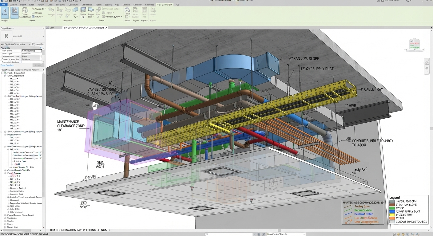
MEP Coordination Drawings are detailed construction documents that show exactly how a building’s mechanical, electrical, and plumbing systems fit together and inside the structure before anyone touches a wrench or conduit bender. They resolve routing conflicts between ducts, pipes, cable trays, and structural elements during design, so your crews don’t discover a sprinkler main running straight through a beam on the jobsite.
If you’ve ever managed a commercial build where the mechanical contractor, electrician, and plumber all showed up with their own shop drawings and nobody’s plans matched anyone else’s, you already understand why MEP Coordination Drawings exist. This article breaks down what goes into them, how the coordination process actually works, and why skipping this step costs owners and GCs real money.
The Core Problem MEP Coordination Drawings Solve
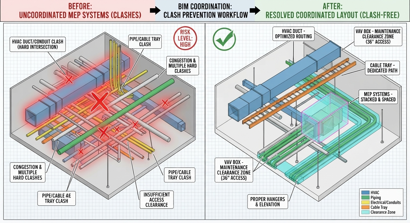
On a typical commercial project, the architect designs the space and the MEP engineers design the systems. Each discipline works from the same base model or drawing set, but they are designing in parallel, not in sequence. The result? Overlapping systems that simply cannot all fit where the plans say they should.
A supply air duct at 24 inches deep, a plumbing waste line at 6 inches, a cable tray, and a fire suppression main might all be routed through the same 30-inch ceiling plenum. The 2D plan set rarely catches this. MEP Coordination Drawings exist precisely because 2D coordination on complex buildings is nearly impossible to do reliably by eyeballing plan overlays. Accurate coordination also depends on understanding structural components, reinforcement layouts, openings, and embeds, which is why detailed structural documentation such as rebar detailing services is important during preconstruction planning.
What Is Actually Inside MEP Coordination Drawings
A coordinated set typically includes several views and data layers:
- Composite plans showing all MEP systems overlaid on a single background, floor by floor
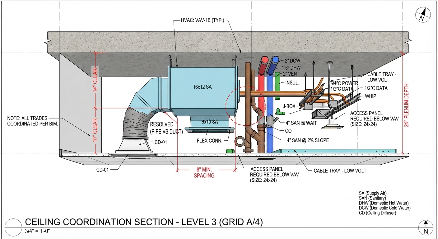
- Coordinated section views at congested areas above ceilings, in shafts, at mechanical rooms
- Clash detection reports documenting every conflict found and how it was resolved
- Routing priorities and zone assignments showing which systems receive priority in tight plenums based on project requirements, constructability, slope, clearance, and system constraints.
- Elevations and dimensions so installers aren’t guessing offsets
- Access and maintenance clearances for valves, dampers, filters, and control panels
The drawings answer practical questions installers actually ask:
- Where exactly does this pipe turn?
- How much clearance do I have above the corridor ceiling?
- Which trade’s work goes in front of the others at this wall penetration?
The BIM Difference: Why 2D Overlay Is No Longer Enough
Twenty years ago, coordination meant laying vellum or CAD sheets on a light table and tracing conflicts by hand. Today, most meaningful coordination happens in a federated BIM model, and MEP Coordination Drawings are the documented output of that process. Autodesk’s BIM coordination materials emphasize early clash identification, model aggregation, issue resolution, and reducing downstream rework, which aligns with this model-based coordination approach. The modern workflow looks like this:
- Model aggregation: Each trade submits its design-intent or shop model to the coordination lead. Structural rebar detailing services provide reinforcement information needed to account for structural elements during MEP routing.
- Clash detection run: Software like Navisworks scans every combination of systems against each other and against the structural and architectural models.
- Coordination meetings: Weekly (sometimes twice weekly on fast-track jobs), trades meet around the model, walk through every hard clash and soft clash, and assign resolutions.
- Model revision and re-clash: Fixed geometry goes back in, another clash run confirms nothing new was introduced.
- Drawing extraction: Approved coordinated geometry is extracted into MEP Coordination Drawings, the 2D deliverable that subcontractors fabricate and install from.
This is where clash detection services earn their keep. A hard clash (duct intersecting beam) gets caught almost automatically. Navisworks Clash Detective can identify and report cross-discipline interferences earlier in the design process, helping teams resolve coordination issues before construction.
MEP Coordination Drawings vs. Shop Drawings: What’s the Difference?
This confuses a lot of people so let’s clear it up.
Aspect | Coordination Drawings | Shop Drawings |
| Purpose | Resolve routing conflicts between trades | Show how one trade’s system gets fabricated and installed |
| Produced By | BIM/coordination team with input from relevant trades | Individual subcontractors or trade-specific fabricators |
| Content | Multiple MEP systems shown together in coordinated views | One trade’s system shown in fabrication and installation detail |
| Timing | Prepared during the coordination process before installation begins | Prepared for fabrication and installation typically after design and coordination requirements are established |
| Who Uses Them | GCs, BIM/coordination teams, MEP trades, and project stakeholders. | Fabricators, subcontractors and installers |
The two documents work in sequence. MEP Coordination
Drawings come first as it establishes where everything goes. Shop drawings then show how each individual system gets built within those approved routes. If a shop drawing conflicts with the coordinated set, the discrepancy should be resolved through the project’s established review, submittal, and RFI process before fabrication or installation begins.
The Real Cost of Skipping Coordination
Unresolved MEP clashes can become expensive once construction is underway. Even setting aside specific cost estimates, any superintendent with a few commercial projects under their belt has the stories: the return duct that had to be rerouted after drywall was up, the chilled water line that didn’t fit over the corridor ceiling, or the electrical room where panels couldn’t open because a pipe ran across the front.
- A field clash discovered during installation can lead to additional labor, materials, rerouting, demolition, and schedule delays, with the impact increasing when finished work is already in place.
- A clash identified during preconstruction can typically be reviewed and resolved through coordination and drawing revisions before fabrication or installation begins.
Multiply those issues across a complex building, and MEP Coordination Drawings become a high-value part of the preconstruction budget. The less obvious costs matter too: schedule delays, change orders between trades fighting over who pays for the rework, inspection issues, and the credibility hit when an owner watches their project stall over something that should have been caught months earlier.
Who’s Responsible for Producing Them?
On most commercial projects, the responsibility lands in one of three places:
- The general contractor’s BIM department
- A third-party coordination firm
- The lead MEP subcontractor
How to Read MEP Coordination Drawings (A Quick Guide for Owners and PMs)
Even if you never draft a line, you should be able to sanity-check a coordinated set. Here’s what to look for:
- Does the set include every floor and congested area?
- Are gravity systems properly coordinated?
- Are clearances called out?
- Does the drawing reference the coordination model?
The Bottom Line
MEP Coordination Drawings are the bridge between design intent and field reality. They turn a pile of discipline-specific plans into one coherent, buildable picture and they do it at a drafting desk instead of a jobsite. They resolve conflicts during preconstruction, where changes are generally less disruptive and less costly than field rework. Projects that invest in real coordination, run by people who understand both the software and the field, consistently deliver on schedule with fewer change orders and fewer surprises. Projects that treat coordination as a checkbox exercise tend to find out why it’s not one.
Get Your Coordination Done Right the First Time.
At Engineering Geni Mep drafting services, we produce coordinated MEP drawing sets for commercial projects across the USA working from your models or building them from your contract documents. Our drafters and BIM coordinators have sat on both sides of the coordination table, so we understand what installers actually need when they’re standing on a ladder at 6 a.m. trying to read a section detail.
FAQs About MEP Coordination Drawings
Q: What are MEP coordination drawings in construction?
Ans: MEP coordination drawings are construction documents that show mechanical, electrical, plumbing, and fire protection systems together in a coordinated layout. They help identify routing conflicts and establish where each system will be installed before construction.
Q: Who prepares MEP coordination drawings?
Ans: They are typically prepared by a general contractor’s BIM team, a coordination firm, or an MEP subcontractor with input from the affected trades. The final drawings reflect the routing and coordination decisions agreed upon during the project.
Q: What is the difference between MEP coordination drawings and shop drawings?
Ans: MEP coordination drawings show how multiple building systems fit together, while shop drawings provide detailed information for fabricating and installing a specific trade’s system. Coordination addresses where systems go; shop drawings explain how a system is built and installed.
Q: Why are MEP coordination drawings important?
Ans: MEP coordination drawings help identify system conflicts before installation, reduce field rework, and improve coordination between trades. They also give installers a clearer, coordinated layout to work from.
Q: What is included in MEP coordination drawings?
Ans: A coordinated set may include composite MEP plans, sections, elevations, dimensions, equipment locations, routing information, clearance requirements, and details for congested areas such as ceilings, shafts, and mechanical rooms.
Q: Are MEP coordination drawings required by code?
Ans: Not universally by building code by that specific name. Requirements depend on the project’s contract documents, specifications, BIM requirements, and local authority. Many commercial projects use coordinated drawings or models to resolve system conflicts before installation.
Q: Can MEP coordination be done without BIM?
Ans: Yes. Coordination can be performed using 2D drawings, but BIM-based coordination makes it easier to visualize systems in three dimensions, identify spatial conflicts, and coordinate changes between trades.
Q: What is clash detection in MEP coordination?
Ans: Clash detection is the process of identifying conflicts between MEP systems and other building elements, such as ducts intersecting beams or pipes occupying the same space as cable trays. These conflicts can then be reviewed and resolved before installation.



[…] foundations, framing, roofing, insulation, drywall, finishes, and MEP. For MEP-related work, MEP coordination drawings can help provide a coordinated view of mechanical, electrical, and plumbing systems before […]